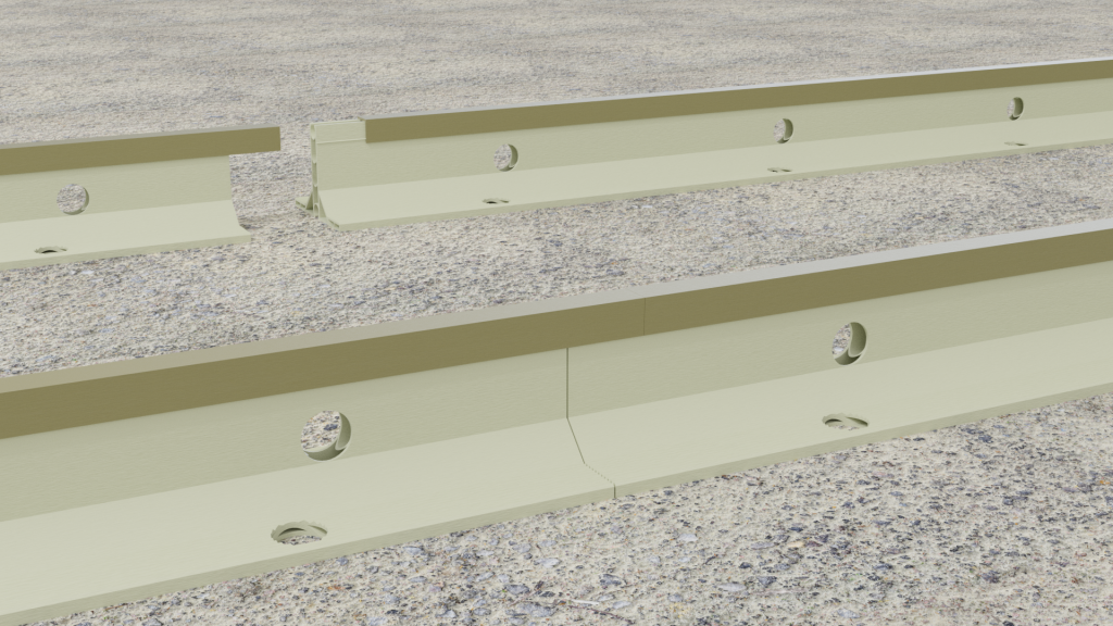
Place a string line along where the rails are to be positioned.
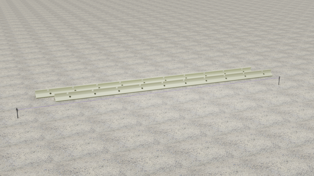
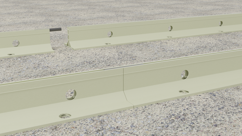
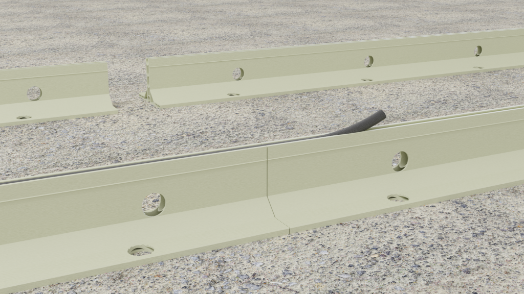
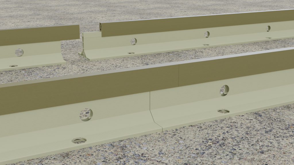
Position rails and connect together with either Compressible Rubber Cord, Straight Coupler Ferrules, Top Cap, or Top extender as required – ensure all rails are butted tightly together.
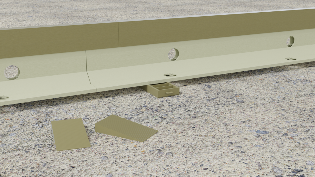
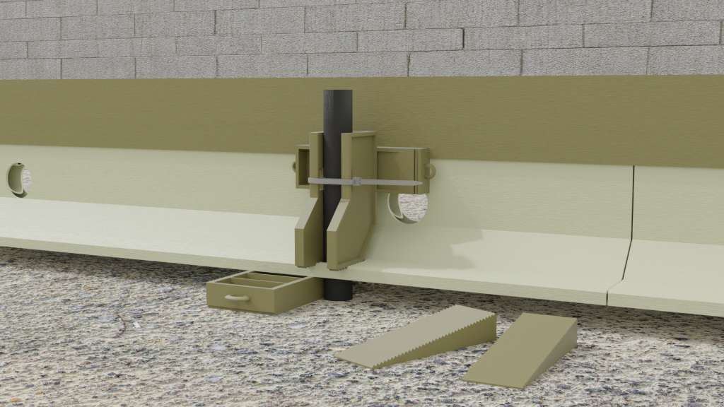
If extra height is required, place a pair of wedges under the rail base, close to where the pins are to be driven through, adjust to height required.
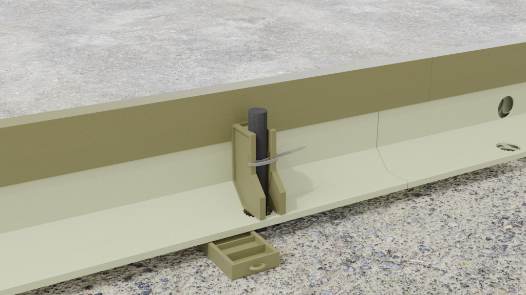
Take the Pin Clamp body and pass a Zip Tie loosely through, connecting the ends together for later tightening.
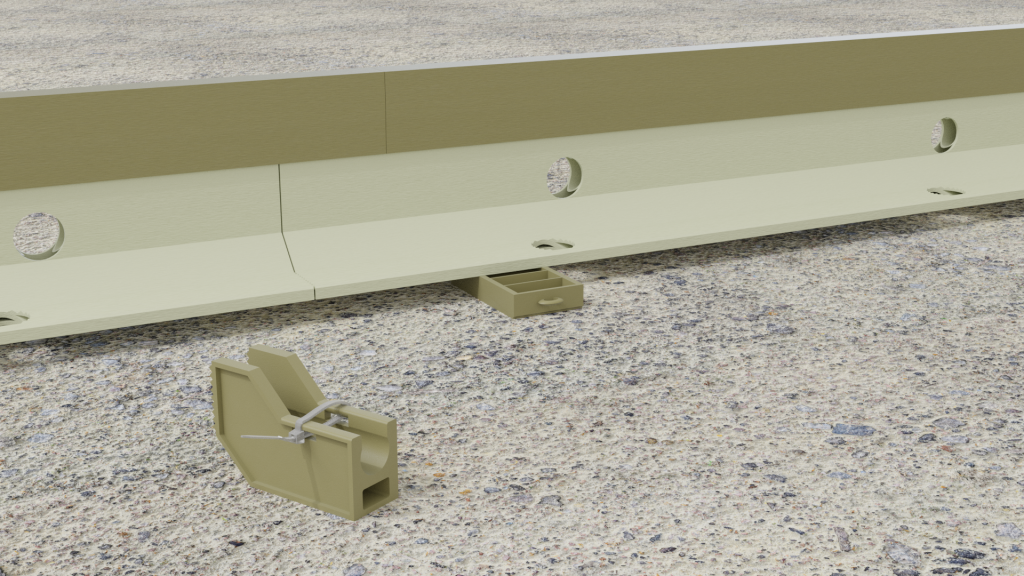
Insert the pin into the Clamp body, ensuring the tie is loose enough to allow the body to slide along the pin.
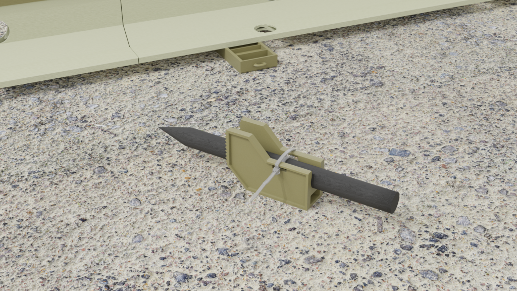
Position pins in holes on larger rails, or close to the rail base edge on the small rail, drive into sub base to desired depth.
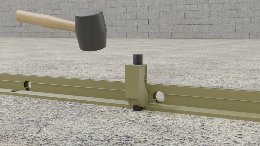
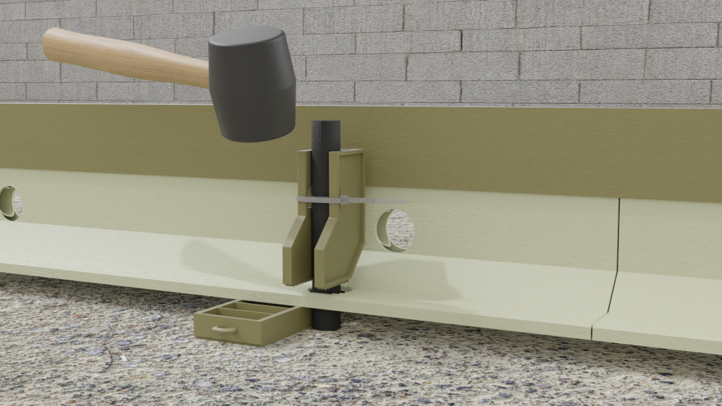
Push Clamp Bodies down hard, so that the teeth on the bottom engage and interlock in the ridges on the rail base, then tighten zip tie to prevent clamp body moving.
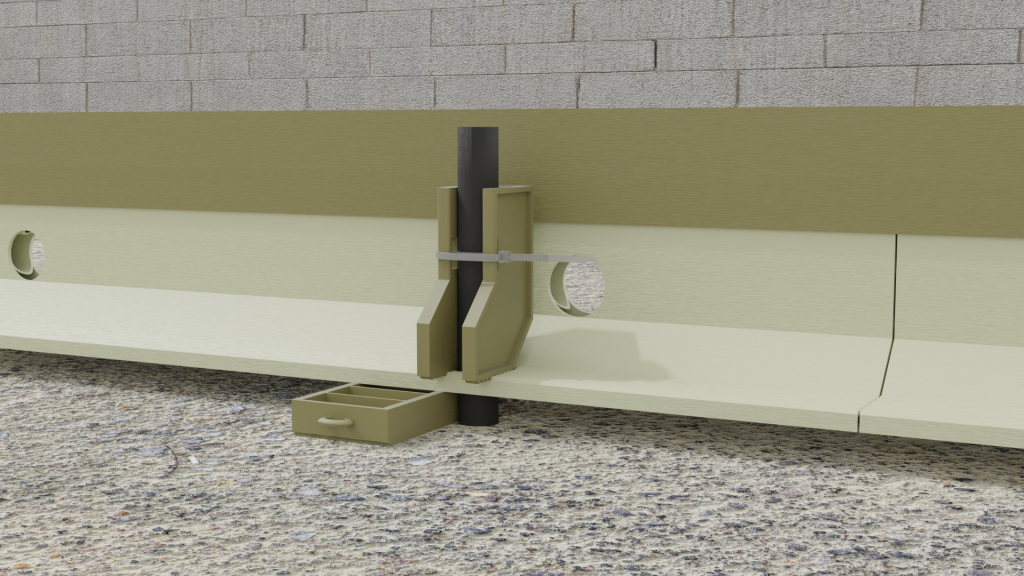
Tap Clamp Body gently down to ensure a secure fixing, if using the larger rails, a pair of wedges can be inserted between the vertical blade and the clamp body or pin, to stiffen and avoid bending of the blade if required, for when large vibrating screed machines run along it.
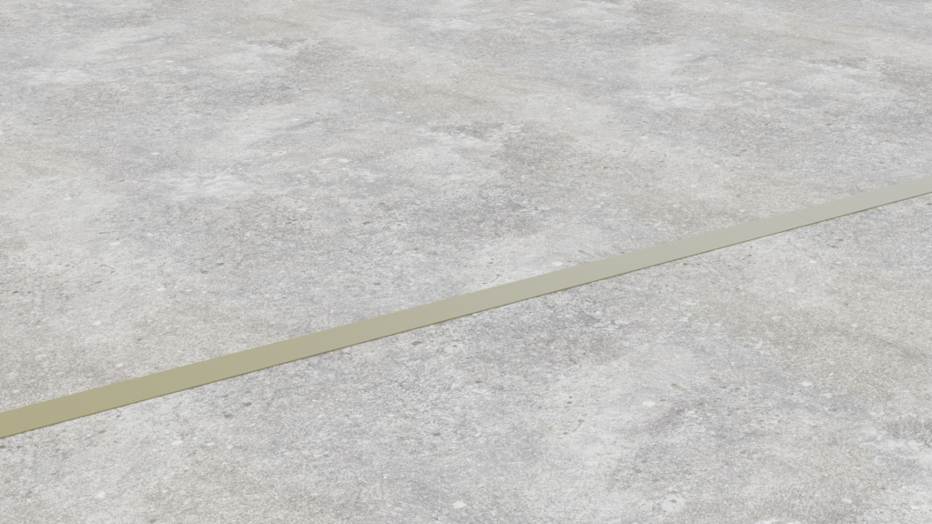
Screeds/slabs can now be installed either side of rails – both side simultaneously if required.
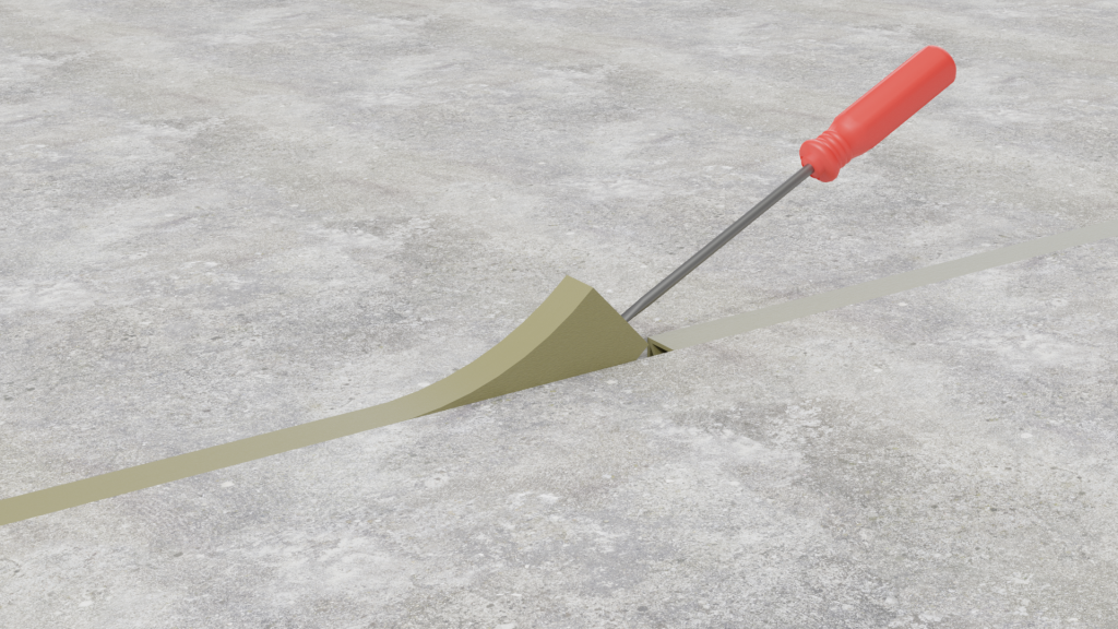
After the new slab/screed has hardened sufficiently, the Top Strips or Extenders can be removed for re-use, simply pop/lift off using a screwdriver at one end to break the seal and free the strips. – or alternatively leave in situ if required.
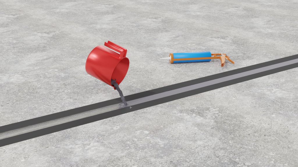
With the slabs/screeds now installed and hardened, if a joint filler is to be used, simply remove the caps and “Hook” out the Ferrules, then pour the flexible joint filler into the top void of the rails, level with the slabs/screeds.